Introduction
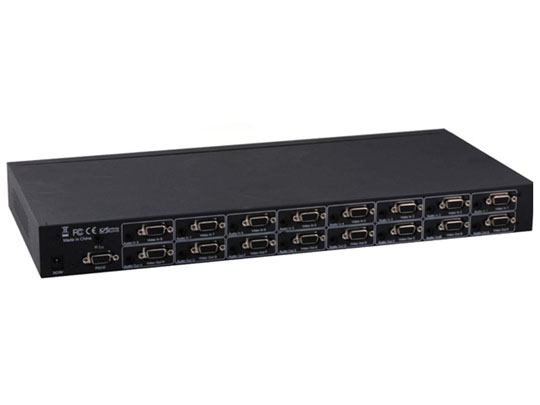
The VGA Switch Splitter routes high quality VGA video and stereo audio from any of eight VGA and audio sources to any of eight VGA displays and audio receivers. Eight outputs give you the choices of sending audio and video signals up to eight displays in any combinations. Any eight to any eight true matrix switching allows for maximum versatility for integrated systems. It eliminates the need to disconnect and reconnect sources to a display equipped with one input. It works with a wide variety of VGA sources such as computers, security cameras and DVRs.
Every source is accessible at all times by any display by selecting it with an IR remote, front panel buttons or through RS232 port.
Features
This product has many features that enable it to perform in a superior manner. Among those features you will find:
Allows any VGA display with audio to view any source with audio at any time
Allows any source with audio to be displayed on multiple displays with audio at the same time
Each display's inputs can be switched with the IR remote control, front panel buttons or through RS232
Supports highest video resolution 1920x1200, 1080p at 60Hz.
Supports highest video Amplifier Bandwidth to 500MHz
PACKAGE CONTENTS
Before attempting to use this unit, please check the packaging and make sure the following items are contained in the shipping carton:
1) Main unit.
2) 5V/3A DC Power Supply.
3) Remote Control.
4) IR extender (Infrared Extender).
5) User’s Manual.
CONNECTION
Before installation, please make sure all devices you wish to connect have been turned off.
1) Connect all source devices to the video and audio inputs on the VGA Switch Splitter
Connect the VGA displays and audio receivers to the outputs on the VGA Switch Splitter.
Connect the 5VDC power supply to the VGA Switch Splitter.
Turn on the Power
Note: 1) Please make sure to cut off the power before inserting IR Extender to the unit.
2) Please make sure to insert the plug of IR Extender to the unit completely.
Attention: Insert / Extract cable gently.
OPERATION
Control the product by buttons
Eight buttons on the Switch Splitter are used to select source devices circularly for outputs A, B, C, D, E, F,G, H. Once the button is pressed, it will select the next source device.
Control the product by IR remote
①Power button
The power button of the IR remote can control the power of the Switch Splitter. When you press this button, the power-on unit will be turned off. If you press it again, the unit will be turned on.
②How to select input 1-8 for output A-H
For example: the action of selecting input 1 for output A is as follows:
First press “A”, then press “1” within 5 seconds, and input 1 will be selected for output A.
The action is the same for selecting other inputs and outputs
③How to turn off output A-H
For example: the action of turning off output A is as follows:
Press “OFF” in the “A” column, you will turn off output A
The action is the same for turning off the other outputs.
④How to turn on output A-H
For example: the action of turning on output A is as the following two ways:
Press “ON” in the “A” column and output A will be turned on.
Or press “A” and “the number” of the input selected last time, output A can also be turned on.
The action is the same for turning on other outputs.
Control the product by RS232
①Introduction of RS232 remote operation:
RS232 remote operation is mainly based on the “super terminal” of Windows operation system. Its parameter should be: ANSI 4800 8-N-1-non
②Setting of “super terminal” interface
a. Connect the switch splitter to the COM of PC with a RS232 cable.
b. Choose the right COM when you setting “super terminal” and then set the parameter as follow:
Baud frequency:4800
Data bit: 8
Parity bit: N
Stop bit: 1
Data stream: NON
③The method of instruction input
Input your instruction and the instruction should be letters, numbers, and finished with “Enter” button.
Please input the next instruction in three seconds or the ”Overtime instruction” will appear.
The input instruction should be right, or you will be rejected with the “wrong instruction”
If the input or output that you choose is not connected to devices or not in power-on mode, “ineffective instruction” will inform you.
If your instruction is performed, you can see the instruction of “successful operation”.
④Instruction form
|
Instruction
|
Function
|
|
QS
|
This order enables you know which inputs and outputs are available and the connection of inputs and outputs.
|
|
PON
|
Turn on power of the product
|
|
POFF
|
Turn off power of the product
|
|
A1,A2,A3,A4,A5,A6,A7,A8
|
Select input 1-8 for output A respectively
|
|
B1,B2,B3,B4,B5,B6,B7,B8
|
Select input 1-8 for output B respectively
|
|
C1,C2,C3,C4,C5,C6,C7,C8
|
Select input 1-8 for output C respectively
|
|
D1,D2,D3,D4,D5,D6,D7,D8
|
Select input 1-8 for output D respectively
|
|
E1,E2,E3,E4,E5,E6,E7,E8
|
Select input 1-8 for output E respectively
|
|
F1,F2,F3,F4,F5,F6,F7,F8
|
Select input 1-8 for output F respectively
|
|
G1,G2,G3,G4,G5,G6,G7,G8
|
Select input 1-8 for output G respectively
|
|
H1,H2,H3,H4,H5,H6,H7,H8
|
Select input 1-8 for output H respectively
|
|
OFFA,OFFB,OFFC,OFFD,OFFE,OFFF,OFFG,OFFH
|
Turn off output A-H respectively
|
|
ONA,ONB,ONC,OND,ONE,ONF,ONG,ONH
|
Turn on output A-H respectively
|
|
Note: Every instruction must be finished with pressing "Enter" button.
|
|